[통신]

Understanding the VME Interrupt and Signal Acknowledge Cycle

Neo Park 2012. 11. 21. 11:11


The VME bus specification defines the Priority Interrupt Bus so that a VME device can asynchronously request service from a controller. This gives a VME/VXI device a way of getting the controller’s attention at any time.


A VXI/VME bus system has seven interrupt lines physically connected to all slots in the chassis. This document addresses interrupts on both VME and VXI systems.


Interrupt line 7 has the highest priority, and interrupt line 1 has the lowest priority. In addition to the actual interrupt lines, the Priority Interrupt Bus also consists of a daisy-chained interrupt acknowledge signal and parts of the Data Transfer Bus (the data lines, the data acknowledge line, and the lower three address lines). The table below summarizes each signal used in the Priority Interrupt Bus and summarizes the function of each signal. A device that requests service by asserting one of the interrupt lines is known as an interrupter. A functional device known as an interrupt handler services the interrupt. There can be more than one interrupt handler in a VXI/VMEbus system.  


Table I. Priority Interrupt Bus Signals


Signal

Function

IRQ1*-IRQ7*

An interrupter uses this signal to indicate that it is requesting service.     

IACK*

An interrupt handler uses this signal to indicate that it has received an interrupt and is ready to receive a status/ID that will tell the handler how to proceed with servicing the interrupt.

IACKIN*/

IACKOUT*

A module receives the IACK* on IACKIN*. It places a status/ID on the bus if the interrupt level being serviced matches the module’s interrupt level and if the device is interrupting. Otherwise, the module passes the signal on using IACKOUT*.

A01-A03

The interrupt handler asserts these lines with the value corresponding to the interrupt level being serviced.

D00-D31

The interrupter being serviced places the status/ID on these lines once IACK* has been received.

DTACK*

The interrupter uses this signal to indicate that its status/ID is asserted on the data lines.


A more detailed explanation of what happens in the interrupt cycle is outlined below.

A device that requests service by asserting one of the interrupt lines is known as an interrupter. A functional device known as an interrupt handler services the interrupt. There can be more than one interrupt handler in a VXI/VME bus system. However, there can only be one interrupt handler per interrupt level in the system. 

Therefore, two types of interrupt handler systems are possible:

I. A single handler system
II. A distributed system

In a single handler system, one interrupt handler device services all interrupt lines. In a distributed system, there are two or more handlers, each servicing an exclusive subset of the seven interrupt lines.
Most systems are single handler systems, where the system controller handles all interrupt lines in the chassis.  

There are two types of interrupters:

I. Release on ACKnowledge (ROAK)
II. Release on Register Access (RORA)

Most VXI and VME instruments fall under the ROAK category and the sequence of events described below is only applicable to ROAK devices.


The Sequence of Events During an Interrupt (IACK*) Cycle

1. After a device asserts an interrupt, it waits for a response from the interrupt handler.

2. When the interrupt handler detects that an interrupt line has been asserted, the interrupt handler asserts the IACK* (interrupt acknowledge) signal.

3. It also sets the lower three address lines A01 – A03 to indicate which interrupt line it is trying to acknowledge with the IACK* signal. 

4. The IACK* line that the handler drives is connected to the IACKIN* pin of slot 0 in the chassis (Slot 1 in VME bus systems). 
    If the module in the first slot is not asserting the interrupt line being acknowledged, the module must propagate the IACK* signal to its IACKOUT* pin, which is connected to the next slot’s IACKIN* pin. The propagation of the IACK* signal from slot to slot continues until the IACK* signal reaches the first module that is interrupting on the line being acknowledged. When the interrupter sees IACK*, it places its status/ID on the data/bus.

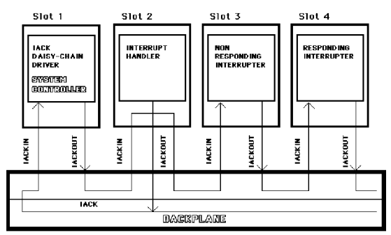
The interrupt handler reads the status/ID. Because the interrupt lines are open collector lines, more than one device can assert the same interrupt line at the same time. Therefore, the module asserting the interrupt does not propagate the IACK* signal. This action prevents other devices that are interrupting on the same line from getting the IACK* signal and attempting to respond at the same time. After the interrupt handler services the interrupter, the interrupter releases the line. If other devices are interrupting on the same line, the handler then begins another interrupt acknowledge cycle to service the next interrupter on that line. The following figure illustrates the interrupt acknowledge daisy-chain.


Figure 1. Interrupt Acknowledge Daisy-Chain
Note: RORA devices require you to read/write a device specific register in order to complete the interrupt acknowledge cycle.

In this figure, the device in slot 4 has asserted an interrupt. 
The figure shows that if more than one device asserts the same interrupt line, the device closest to slot 0 (slot 1 in VME) has the highest priority for interrupt service because it receives the IACK* signal first. 
The next closest device has the next highest priority, and so on. It is important to remember that the IACK daisy chain must be connected across unoccupied backplane slots, or else interrupts coming from devices to the right of the empty slot will not be acknowledged. 
Most chassis have jumperless backplanes where this daisy-chain connection happens automatically. However, on older backplanes that are jumpered, jumpers must be used to connect the IACK daisy chain across unoccupied slots. on jumpered backplanes, you should also pull the jumpers from the occupied slots so that the IACK daisy-chain is not mistakenly connected through the slot containing the interrupter.


'[통신]' 카테고리의 다른 글

CAN Transceiver : Application (TI : SN65HVD230,231,232)  (0) 2012.11.22
CAN(Controller Area Network) 개요  (0) 2012.11.22
VMEbus에 대하여  (0) 2012.11.15
VME bus Description : VME 버스란?  (0) 2012.11.14
bps와 baud  (0) 2012.10.29